Wireless RX

$13.00 USD

As an extension to the Wireless Gameboy/GBA Controller project, this receiver which allows you to control your GBA wirelessly after you hook up all the keys to the board. You will need a board and transmitter as a minimum to get started. You can continue to play the GBA as normal too if you wish. Measures 27x24x2.8mm.

New v1.1 now has the option of X/Y buttons.
Only works with our transmitters.

Want a simpler install on the DS Lite? We have a flex board available.

Questions? Jump on our Discord server where we and other users can help you or contact us via Twitter.

This is a DIY part which requires a fair bit of work. and it draws about 15mA. You’ll need to make some modifications to your GBA firstly by adding a wire to each button, some cutting to the case.

Could work on the GBC, GBA SP, Micro, etc, you just need to confirm the buttons on the device are common ground, at 3.3v when not being pressed and you just need to figure out the wiring of the buttons yourself and find a 3.3V voltage source on the board.

10 ready to build (5-10 days build time) (can be backordered)

Category:

Description

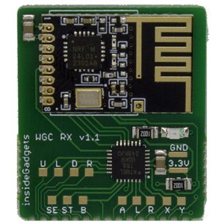
You will need a board and receiver as a minimum to get started. You can re-using your existing transmitter if you already have one.

You can have multiple receivers per transmitter and you can use the same receiver for different wireless controllers. Any receivers/transmitters you purchase will be paired together. If you are unsure about your use case, please send us a quick email to support@insidegadgets.com.

Transmitters available

To prevent double listing of transmitters, you should purchase them from their listings:

Please note that there is no encryption or security available for these devices, while this should pose no issue for home users, it would be possible for an attacker to potentially take over your controls or block your control.

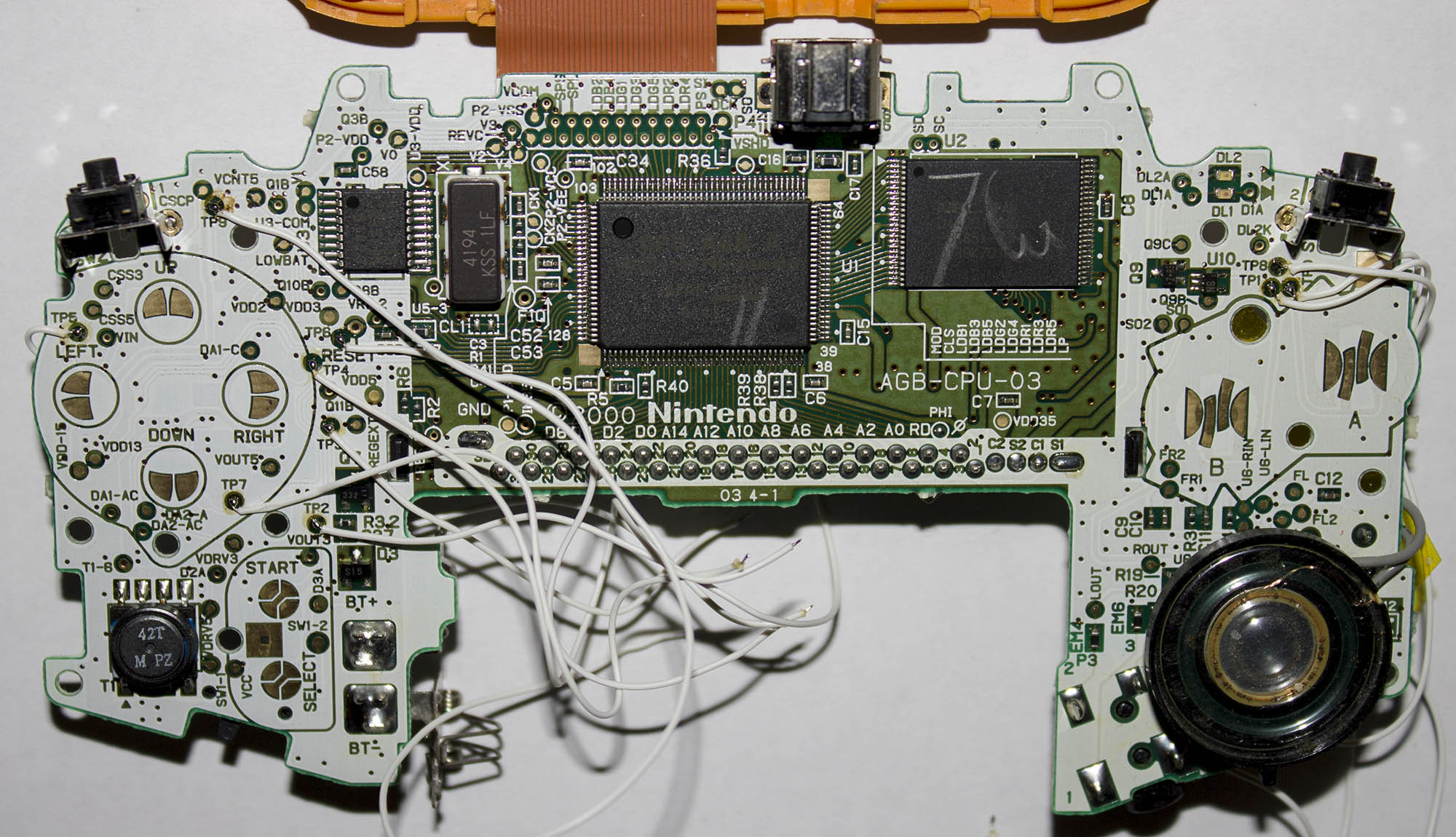
Demo video shows a specially modified SNES controller.

Additional information

Weight 5 g

Installation

1. Take apart your GBA and connect some wires to all the points shown in the image. TP0, TP1, TP2, TP3, TP4, TP5, TP6, TP7, TP8, TP9.

2. Wire up the points to the board.

TP0 = A
TP1 = B
TP2 = SL (Select)
TP3 = ST (Start)
TP4 = R (Right)
TP5 = L (Left)
TP6 = U (Up)
TP7 = D (Down)
TP8 = R (near A on board) – Right trigger
TP9 = L (near A on board) – Left trigger

3.3V = SIN pin on the cart connector
GND = System GND

Reviews

There are no reviews yet.

Only logged in customers who have purchased this product may leave a review.