Description
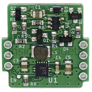
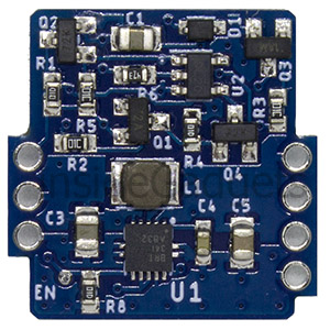
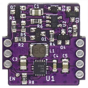
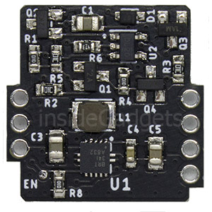
Note: This board only supplies the 5V power rail – no LCD voltage are generated so this board won’t work with the original screen, only aftermarket kits. This board is only a proper replacement if you have modded your system with a modern IPS kit.
Using with a Game Boy Color or Game Boy Pocket
If you wish to use this on an original Game Boy system, you must:
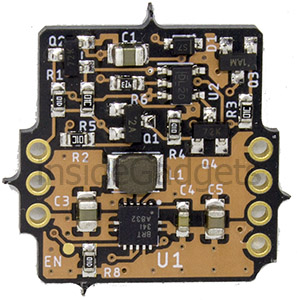
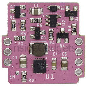
- Remove U5 from the Game Boy circuit board (the DC/DC converter board) and replace it with this one. Make sure you have a header pin populated for pin 2 on the socket!
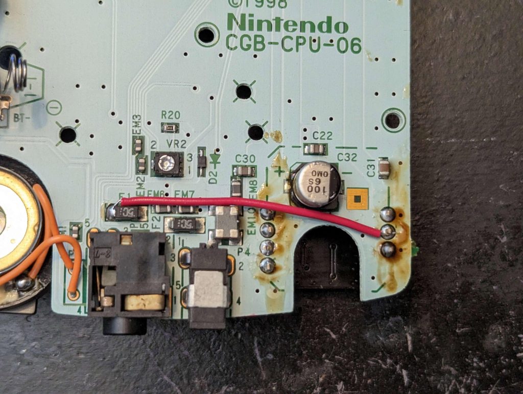
- On the main Game Boy PCB, add a wire from pin 2 of the U5 socket to the node labelled SW1-VCC. This node connects to the power switch and F1, so you can choose either points. Note that Game Boy Pockets do not have pin 2 available, so you must run a wire directly from the Pocket Mouse Power Board’s pin 2 instead.
- If you are soldering a wire to the fuse directly, MAKE SURE YOU CHOOSE THE CORRECT SIDE. It must be the side that’s directly connected to the power switch. A multimeter will not tell you which side of the fuse is which if you have the fuse on the board.

Reviews
There are no reviews yet.